
1.5T汽油机曲轴设计与开发(含CAD零件图,SolidWorks三维零件图)

1.无需注册登录,支付后按照提示操作即可获取该资料.
2.资料以网页介绍的为准,下载后不会有水印.资料仅供学习参考之用.
密 惠 保
1.5T汽油机曲轴设计与开发(含CAD零件图,SolidWorks三维零件图)(任务书,开题报告,文献摘要,外文翻译,论文说明书12000字,CAD图2张,SolidWorks三维零件图1张,答辩PPT)
摘要
曲轴作为发动机重要部件之一,工作条件恶劣,对发动机的工作性能和寿命有重大影响。曲轴的破坏有80%是弯曲疲劳引起的,在设计过程中要重点关注曲轴的形状、尺寸、结构、材料等参数。因此,本文对曲轴进行设计和分析,其工作对现代汽车发动机设计有着一定的参考意义。
本文通过理论计算,得到曲轴结构参数,并建立曲轴的三维实体模型;通过数值仿真模拟的方法对曲轴应力分布和变形情况进行研究,对汽油机曲轴进行验算。基于曲轴的实际工作情况,建立其静力学分析模型,获得曲轴在发动机最大转速工况下的应力分布和变形情况;基于分析结果,进行曲轴可靠性的探讨,为结构改进和优化提供参考,以降低零部件失效风险。
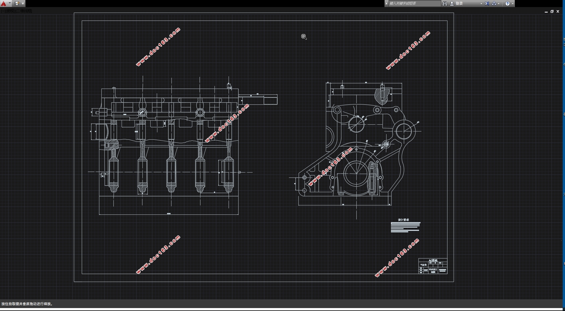
首先,进行曲轴结构设计。根据已有四缸汽油机的数据,利用理论公式的计算和分析,结合现有曲轴设计标准,确定曲轴的结构和尺寸。在本次设计中,曲轴选用材料为球墨铸铁QT800;主轴颈直径为55mm,长度为20mm;曲柄销直径为19mm,长度为49mm;曲柄臂宽度为82mm,厚度为18mm。 [资料来源:http://think58.com]
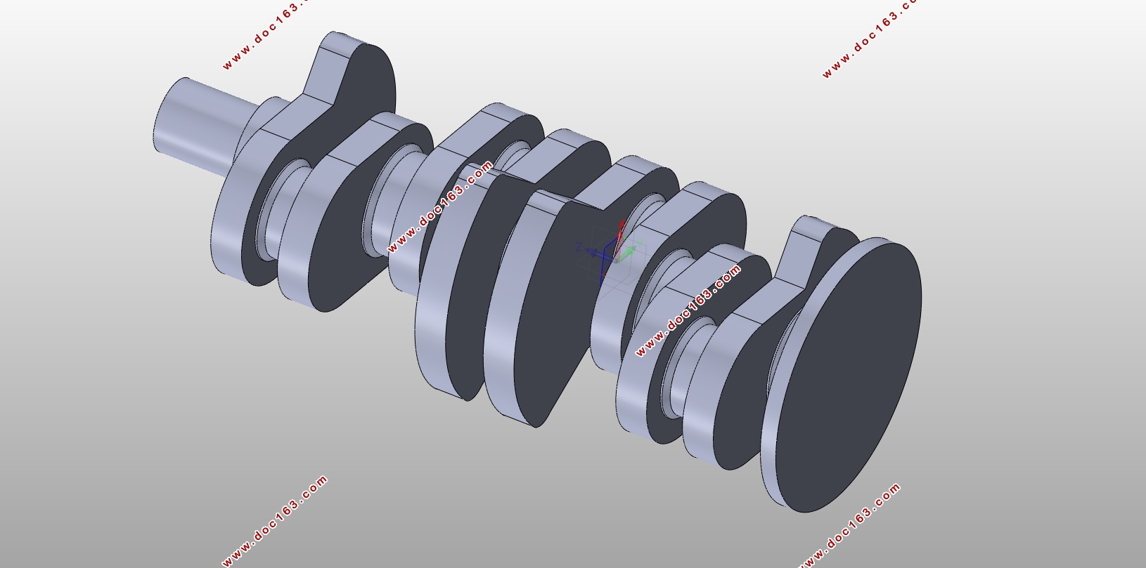
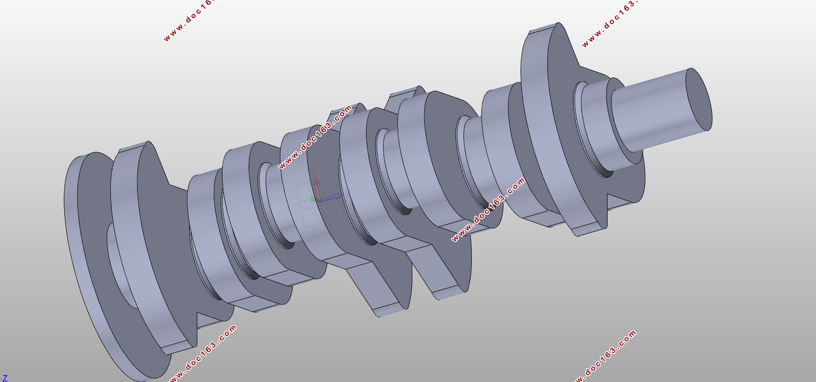
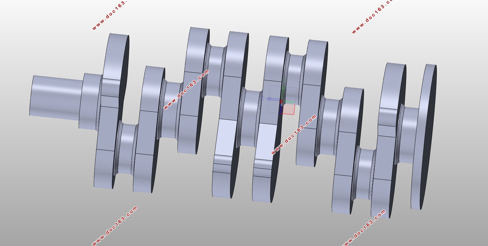
其次,建立四缸发动机曲轴的三维模型。本文基于SolidWorks三维建模软件进行曲轴的三维建模,以曲轴臂为基准,通过拉伸、旋转、镜像等方法建立曲轴模型,主要结构包括有5个主轴颈,4个连杆轴颈、曲柄和平衡重。考虑到建模时的方便,忽略较小结构如油孔。
然后,基于ANSYS有限元软件建立曲轴的静力学分析模型。通过软件中工程材料模块(Engineering Data),赋予曲轴材料属性;建立基于实际工作静力学分析模型。基于Workbench软件完成曲轴的三维网格离散;选择发动机最大爆发压力时刻,作为曲轴受力分析的边界条件,分别在四缸点火时刻添加支撑和应力条件,在主轴颈添加周向约束,考虑到曲轴在最大转速时被卡死时受力最大,故在曲轴两端添加零位移约束,在连杆轴颈添加最大轴向受力;基于等效应力分析的理论对其进行静力学分析,得到其应力分布和变形情况,最大等效应力为136.21MPa,位于第二曲拐上,最大变形量为0.1473mm,位于第一曲拐上。
最后,探讨曲轴工作时的最大转速下的受力变形情况。根据建立的分析模型,实现对曲轴应力分布和变形情况的分析,探讨曲轴的工作可靠性,保证曲轴满足设计目标。
关键字:曲轴;静力学分析;有限元;ANSYS
Abstract
As one of the important components of the engine, the crankshaft has poor working conditions and has a significant influence on the performance and life of the engine. 80% of the crankshaft damage is caused by bending fatigue. In the design process, we must pay attention to the parameters such as the shape, size, structure, and material of the crankshaft. Therefore, this paper designs and analyzes the crankshaft, and its work has certain reference significance for the design of modern automobile engine. [资料来源:THINK58.com]
This paper obtains the structural parameters of the crankshaft and establishes a three-dimensional solid model through theoretical calculation at first. Then, the stress distribution and deformation of the crankshaft are studied through numerical simulation methods. The crankshaft of the gasoline engine is designed and checked. Based on the actual working conditions of the crankshaft, a static analysis model was established to obtain the stress distribution and deformation of the crankshaft under the maximum engine speed conditions. Based on the analysis results, the reliability of the crankshaft was discussed to provide reference for structural improvement and optimization. Reduce component failure risk.
First, design the crankshaft structure. Based on the data of the existing four-cylinder gasoline engine, using the calculation and analysis of the theoretical formula, combined with the existing crankshaft design standards, determine the structure and size of the crankshaft. In this design, the crankshaft was made of ductile iron QT800; the main shaft diameter was 55mm and the length was 20mm; the crank pin diameter was 19mm and the length was 49mm; the crank arm width was 82mm and the thickness was 18mm.
Then, build a three-dimensional model of the crankshaft of a four-cylinder engine. This article based on SolidWorks 3D modeling software for the three-dimensional modeling of the crankshaft, using the crankshaft as a reference, the crankshaft model was established by stretching, rotating, mirroring and other methods, the main structure includes five main journals, four connecting rod journals, cranks And balance weight. Taking into account the convenience of modeling, ignore smaller structures such as oil holes.
Second, based on Engineering Data in ANSYS, material properties are assigned. Establish a static analysis model based on actual work. The workbench software is used to complete the three-dimensional grid discretization of the crankshaft; the maximum explosion pressure moment of the engine is selected as the boundary condition of the crankshaft force analysis. The support and stress conditions are added at the time of four-cylinder ignition and the cylinder constraint is added to the main journal. When the crankshaft is stuck at maximum speed, the maximum force is applied. Therefore, a fixed constraint is added at both ends of the crankshaft, and the maximum axial stress is added to the connecting rod journal. Based on the theory of equivalent stress analysis, the static analysis is performed to obtain the stress. Distribution and deformation, the maximum equivalent stress is 136.21MPa, located on the second crankshaft, the maximum deformation of 0.1473mm, located on the first crook. [资料来源:http://think58.com]
Finally, the deformation at the maximum torque point and the maximum speed of the crankshaft when working is discussed. According to the analysis model established, the analysis of stress distribution and deformation of the crankshaft is realized, and the working reliability of the crankshaft is explored to determine whether the crankshaft meets the design goals.
Key words: crankshaft; statics analysis; finite element; ANSYS
本文对某1.5T汽油机进行曲轴设计和分析,其发动机的缸数、冲程数、点火顺序和基本参数等数据如表2-1所示。
表2-1发动机基本参数
参数名称 参数值
缸数 4
冲程数 4
缸径(mm) 77
行程(mm) 85.8
连杆长度(mm) 138.54
压缩比 9.3
点火顺序 1,3,2,4
[资料来源:www.THINK58.com]

目录
第1章绪论 1
1.1研究背景及意义 1
1.2国内外研究现状 1
1.3软件介绍 2
1.4本文主要研究内容 3
第2章曲轴的结构设计 5
2.1发动机的基本参数 5
2.2曲轴的工作条件及设计要求 5
2.3曲轴的结构形式 5
2.4曲轴的材料选择 6
2.5曲轴的结构设计 6
2.6小结 9 [资料来源:THINK58.com]
第3章曲轴模型的建立 11
3.1建立曲轴模型 11
3.2小结 13
第4章曲轴的静力学分析 14
4.1 曲轴模型的建立和导入 14
4.2曲轴材料属性的设置 14
4.3 曲轴模型的网格离散 15
4.4 网格质量的检验 16
4.5 曲轴的约束条件 16
4.6 有限元求解结果分析 17
4.7小结 22
第5章结论和展望 23
5.1结论 23
5.2展望 23
参考文献 25
致谢 26 [资料来源:http://www.THINK58.com]
上一篇:场地自动驾驶车辆制动系统设计(含CAD零件图装配图,STP三维图)
下一篇:小型电动代步车制动系统设计(含CAD零件图装配图)(英文)