
����(45+70+45m)ԤӦ�����������������������ʩ��ͼ���(��CADͼ)

1.����ע���¼,֧��������ʾ�������ɻ�ȡ������.
2.��������ҳ���ܵ�Ϊ,���غ���ˮӡ.���Ͻ���ѧϰ�ο�֮��.
�� �� ��
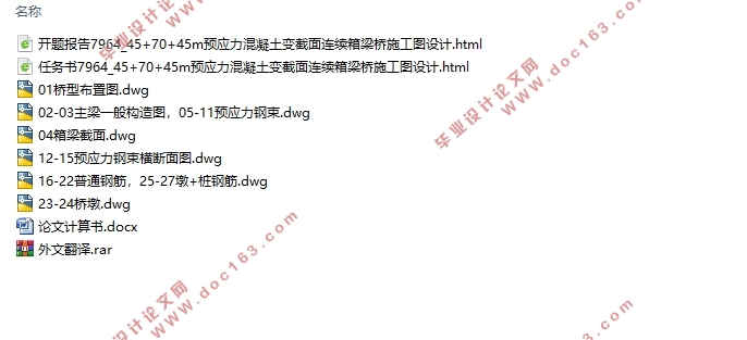
����(45+70+45m)ԤӦ�����������������������ʩ��ͼ���(��CADͼ)(������,���ⱨ��,���ķ���,���ļ�����25000��,CADͼֽ6��)
ժҪ
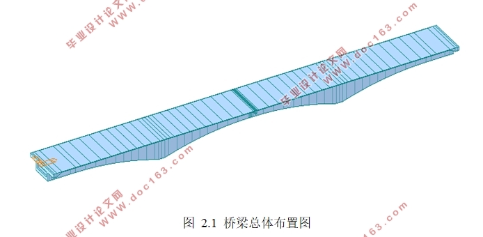
�����ҵı�ҵ��Ƶ���ƶ�����λ���人�еĸ��Ӵ��ŵĵ�����ԤӦ����������������������š��Ҵ˴ε���������Ǹ������ͨ�ù淶�Ĺ涨���㱾���������ŵ��ϲ��ṹ��ͬʱ��Ҫ����²��ṹ�ļ��㲢����ƻ��ƴ������ŵ�ʩ��ͼ��
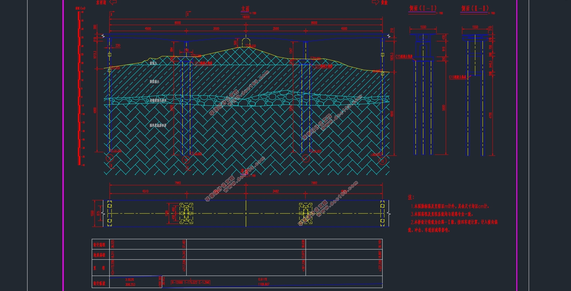
��һ�������չ�·�Ź����ع淶����ȷ����������������Ҫ�����Լ����ϸ���ߴ磬ȷ��֧�㴦�Ϳ��д������ߣ�ȷ���ſ��������ȣ�ȷ���װ���Ե�Լ���Ե�ı仯���ߵķ��̣�ȷ�������ȱ仯����ʽ��
�ڶ��������� MIDAS CICIL ������������ģ�͡����ȸ���֮ǰȷ���Ľṹ�ߴ罨������ģ�ͣ�֮������ԤӦ�������ͺ��أ��ٻ���ʩ���Ρ��������������Ҫ�IJ����ǹ���ԤӦ���������ӣ���Ҫ���з����ĵ��������ҵ�������淶Ҫ���ԤӦ�����������Լ���״��������ɺ�Ϳ������з������鿴�����������µ�����ͼ��Ӧ��ͼ��ͬʱ��PSC����鿴ģ���Ƿ�������η���ѹӦ�����㡢�ֽ���Ӧ�����㡢�������б���濹�������Լ������濹������ȡ�
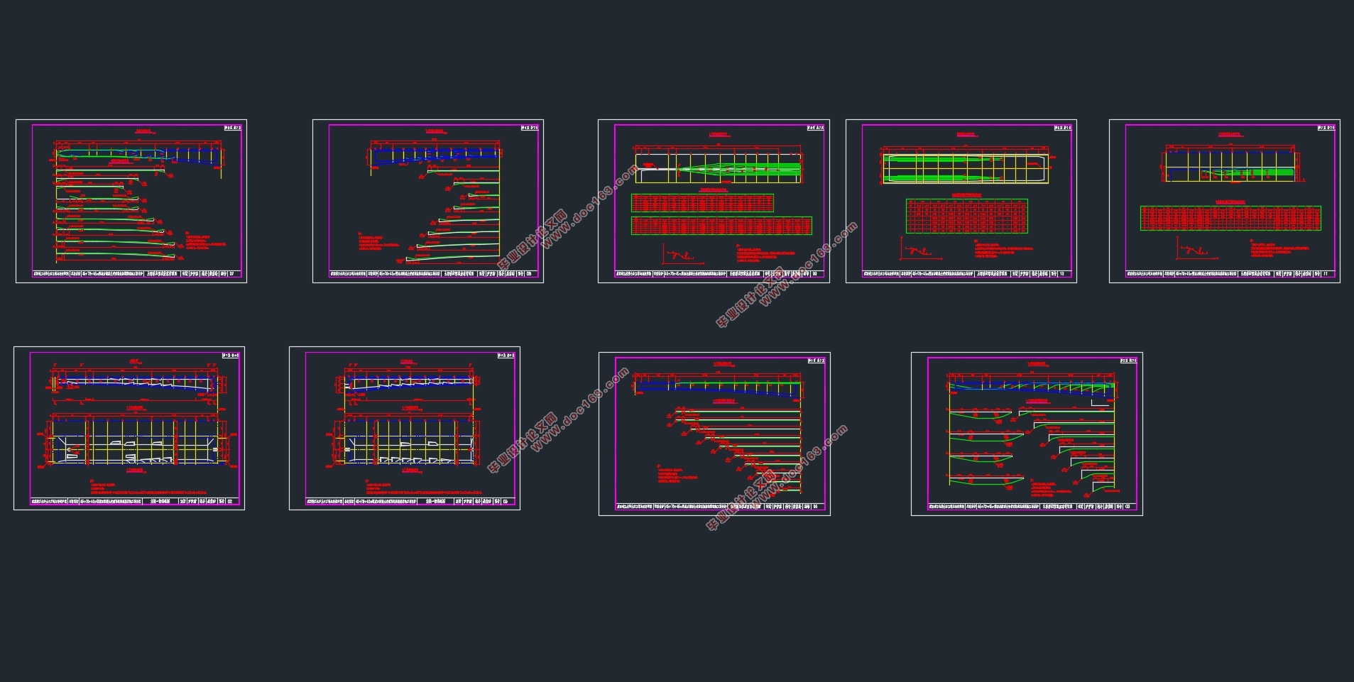
�����������������г�����ij���������ԤӦ������ê�����ݰ�ľֲ���ѹ�����������պ����յĹ�ע���м�������㣬������ɴ������ŵ�ʩ��ͼ�� [������Դ��http://think58.com]
�ܽ����ģ�͵ķ��������㲿�ֵķ������������������Ƶ��ϲ����²��ṹ���㷽����ȷ���־�״��������������״̬ǿ������淶Ҫ��������Լ���ɵĹ���������������������Ҫ��
�ؼ��ʣ������ţ�ԤӦ����������MIDAS CIVIL��ģ����Ƽ��㣻����
Abstract
The object of my graduation project is the third prestressed concrete continuous box girder bridge with variable cross section in Fu River Bridge in Wuhan. My design task is to calculate the superstructure of the continuous box girder bridge according to the relevant General specification, and also to complete the calculation of the substructure and to design the construction drawing of the box girder bridge.
The first step is to determine the main structure of the bridge main beam and the related details according to the relevant specifications of the highway bridge rules, determine the beam height of the pivot point and the middle span, determine the width of the bridge and the thickness of the roof, determine the equation of the change curve of the bottom edge and the upper edge of the bottom plate, and determine the form of the change of the thickness of the web. [��Ȩ���У�http://think58.com]
The second step is to build bridge model by using MIDAS CICIL software. First, the geometric model is established according to the size of the pre-determined structure, then the prestressed steel beams and loads are added, and then the construction stage is divided. The most important step in this process is the addition of the prestressed beam, which requires repeated adjustments to find the number and shape of the prestressed beam that meets the requirements of the specification. After the completion of the debugging, we can run the analysis and check the internal force diagram and the stress diagram under various load combinations. At the same time, the PSC interface can see whether the model satisfies the normal pressure stress checking, the tensile stress checking calculation, the checking calculation of the cross section and the oblique section, and the checking calculation of the normal section.
The third step is to calculate the load-bearing capacity of the bridge deck and the local bearing capacity of the prestressed steel beam anchorage zone, and to calculate and check the cast-in-place pile of the main pier and the main pier, and draw the construction drawings of the bridge. [��Դ��http://www.think58.com]
Summary: through the analysis of the model and the analysis and calculation of the hand calculation, the calculation method of the upper and lower structure of this design is correct. The ultimate state strength of the endurance state bearing capacity is satisfied with the standard requirements. The calculation process and the amount of work completed are in accordance with the requirements of the design task book.
Keywords: girder bridge; Prestressed concrete; MIDAS CIVIL; Design and calculate ; Checking computation
1.1 ���̸ſ�
1.1.1 ���̽���
����λ���人�У����Ӷ������ͻ��飬Ϊ���Ӵ��ŵĵ����������ڸ����š��������Ϊ K3+172.226���յ�Ϊ K3+332.226�������羶����Ϊ �����������¶�Ϊ2%��˫���ij����� ���²��ṹ����˫��ʽ
��
1.1.2 ���ε�ò
��������ò��ԪΪ�Ӻ����ƽԭ����Ҫ�ɵ���ϵȫ��ͳ~�ϡ��и���ͳ����������������������γɡ���·���˵��γʲ�״�������������Ϊƽ�������ɳ���Ģأ��ؼ䶸�������ԣ���Ҫ�ʻ��¹��ɣ��߳���16.7~24.15m����Ը߲�2.0~6.0m����Ҫ���� ��ɣ��Ի���״������״������ȫ��ͳ������������ࡢ����������
[��Դ��http://think58.com]
1.1.3 ����
�ز�����
�ڱ�����̽������ȷ�Χ�ڣ��⽨�������ߵز㰴ʱ������������Ϊ9���࣬���϶��¾���Ϊ��������(Qal)����ֲʿ(Qpd)������ϵȫ��ͳ��������������ճ���� ��ϵ�¸���ͳ���(Q1al) ճ������ɰ����ʯ�㼰��ʯ���� ��ɰ�ң�ʯ̿ϵ��ͳ (C2)�����Ҽл��ң�־��ϵ��ͷ��(S2f) ��ɰ�����ҡ�
1.2 ������ϼ���������
1.2.1 ������
1) ���صȼ�����·-I ����
2) �������ȣ�15.5m��
3) �������I�ࡣ
4) ��ȫ�ȼ���1 ����
5) �����Ҷȣ�����ֵ���ٶ�Ϊ �� ����������Ҷ�Ϊ 7 �ȡ�
6) �߳�ϵͳ��1986����Ҹ̻߳���
���εķ�������ȫ��Ϊ160m���������70m������ԤӦ�����������������š�
[������Դ��http://think58.com]
 [��Ȩ���У�http://think58.com]
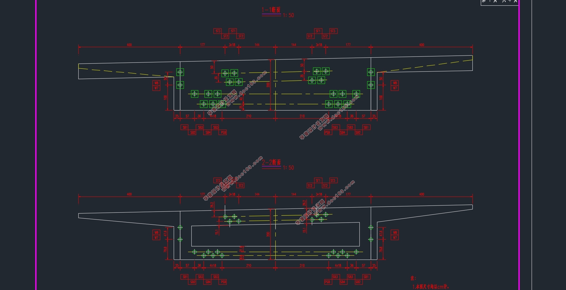
Ŀ¼
��1�� ���� 1
1.1 ���̸ſ� 1
1.1.1 ���̽��� 1
1.1.2 ���ε�ò 1
1.1.3 ���� 1
1.2 ������ϼ��������� 1
[������Դ��http://www.THINK58.com]
1.2.1 ������ 1
1.2.2 ���ϼ�����Ʋ��� 2
��2�� �ſ����岼�ü��ṹ��Ҫ�ߴ��ⶨ 4
2.1�ߴ��ⶨ 4
2.1.1���Ͳ��� 4
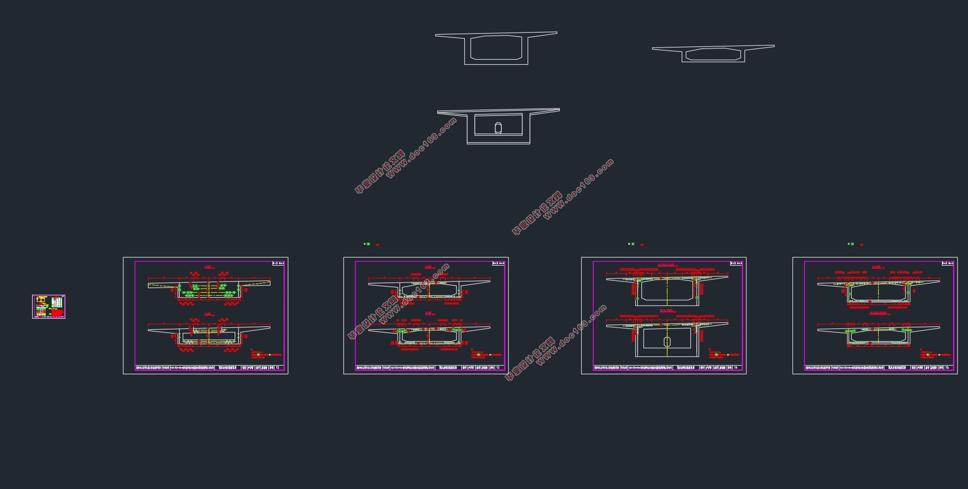
2.1.2 �����ṹ�ߴ� 4
2.1.3 ������װ 6
2.2��������ģ�� 6
2.2.1 ȫ�Žṹ��Ԫ���� 6
2.2.2 ȫ��ʩ���ֶλ��� 7
2.2.3������Ϣ 8
��3�� �������� 11
3.1��������尴�������� 11
3.1.1��������������ȡ1m�İ������� 11
3.1.2�������� 11
3.2������������۰�ļ��� 14
3.2.1��������������ȡ1m�İ������� 14
3.2.2���ز��������� 14
3.2.3������������� 15
3.3������������۰�ļ��� 15
3.3.1.֧�㴦��������ȡ1m���������� 15 [������Դ��THINK58.com]
3.3.2���д���������ȡ1m���������� 16
3.3.3�������� 16
��4�� ����������������� 17
4.1 ���������ļ��� 17
4.2������������ 18
4.2.1����ֲ�ϵ���ļ��� 19
4.2.2���������ļ��� 19
4.2.3������ 19
4.3���������� 22
4.3.1�¶�������������� 22
4.3.2֧��λ��������������� 23
4.3.3���������������� 24
4.3.4Ԥ���������Ĵ����� 25
4.4������������״̬��������� 26
4.5����ʹ�ü���״̬��������� 27
4.6������� 28
��5�� ԤӦ��������������ʧ���� 32
5.1ԤӦ������������ȷ�� 32
5.2ԤӦ�����IJ��� 34
5.2.1����ԭ�� 34
5.2.2�����IJ��� 35 [������Դ��http://THINK58.com]
5.3ԤӦ��������ܵ���֮���Ħ�� 35
5.4ê�߱��Ρ����������ͽӷ�ѹ�� 36
5.5����������ѹ�� 36
5.6ԤӦ��������Ӧ���ɳ� 36
5.7��������������� 36
5.8ԤӦ����������ЧӦ������ 37
��6�� �������� 39
6.1�־�״��������������״̬���� 40
6.1.1������ѹ���߶� 41
6.1.2�����濹����������� 41
6.1.3б���濹������������ 45
6.2�־�״������ʹ�ü���״̬���� 45
6.2.1�����濹������ 45
6.2.2б���濹������ 48
6.3�־�״������Ӧ������ 48
6.3.1���������������ѹӦ������ 48
6.3.2������������ԤӦ��������Ӧ������ 50
6.4����״������Ӧ�������� 54
6.5�Ӷ����� 57
6.6 ����ê�����ľֲ���ѹ���� 58 [��Դ��http://think58.com]
6.6.1�ֲ���ѹ�ߴ�Ҫ�� 58
6.6.2�ֲ���ѹ���������� 59
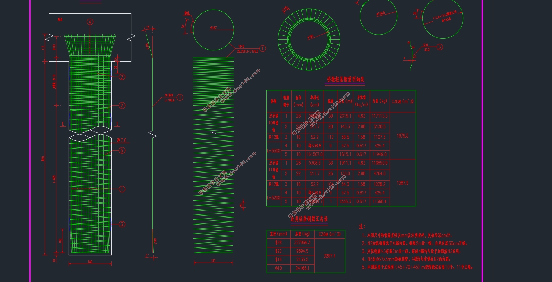
��7�� �²��ṹ���� 61
7.1�Ŷռ��� 61
7.1.1���ؼ��� 61
7.1.2���������� 62
7.1.3����������������� 63
7.2���ע���� 64
7.2.1���ؼ��� 64
7.2.2������ 64
7.2.3���������㣨m���� 65
7.2.4�����������ǿ������ 67
7.2.5�ն�����ˮƽλ������ 69 [������Դ��http://think58.com]
��һƪ�������ŵ�һ��3��25mԤӦ��������С������ʩ��ͼ���(��CADͼ)
��һƪ������ij3��32m���������Žṹ���(��CADͼ)