
一种电能收集充电器的设计(附程序)

1.无需注册登录,支付后按照提示操作即可获取该资料.
2.资料以网页介绍的为准,下载后不会有水印.资料仅供学习参考之用.
密 惠 保
摘 要
随着越来越多的PDA产品的在日常生活中的普及使用,电池充电器的使用也越来越广泛, 一个好的充电器设计,不但能够实时地对充电电路的电压、电流这些关系到充电过程好坏的参数进行检测,针对这些参数的变化调整充电的电流、电压,同时还能在充电电压很小时还能够对电池进行充电。
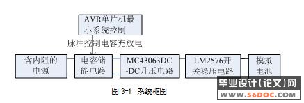
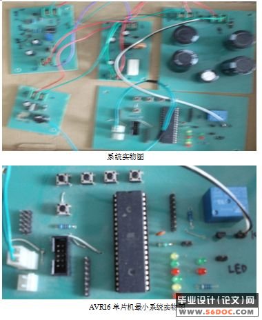
因此,本文设计了一种以MC34063直流升压电路及LM2576直流可调稳压电路为核心,AVR最小系统板为控制电路,能在7.3v-20v范围内的不同输入电压中,通过手动调节可为一定范围内不同电压的电池充电,充电电流Ic达到大于(Es-Ec)/(Rs+Rc)的要求。该系统主要有AVR MEGA16最小系统,44700uf电容组成的电能收集储存电路,MC34063直流升压电路,LM2576直流可调稳压电路组成。系统通过44700uf电容组成的电能收集储存电路从内阻非常大(100欧)的电源中收集并储存电能,再通过AVR MEGA16最小系统于给定时间内发出脉冲使电容放电供给MC34063直流升压电路电压升压,然后由LM2576直流可调稳压电路稳压为内阻较小的(0.1欧)模拟电池充电。本系统具有低功耗,输出稳定可调,输入内阻大,转换效率高无需外部电源供电,低电压启动(7.3v)等特点。
关键词:充电器;电能收集;升压;AVR ATmega16;MC34063;脉冲充电 [资料来源:http://think58.com]
Power to collect charger
Abstract
As more and more PDA products, the increasing use in everyday life, the battery charger is also more widely used, a good battery charger design, not only in real time charging circuit voltage and current of these relations to the charging process for testing the parameters of good and bad for changes in these parameters to adjust charge current, voltage, while the charge voltage of a small be able to recharge the battery, such as outdoor activities, to take advantage of low-voltage or solar power, etc. for charging, the only way to ensure that extend battery life.
For the reason that,we designed a system is centering on MC34063 direct-current boosting circuit and adjustable LM2576 direct-current stabilivolt circuit. AVR monolithic machine minimum system board is a control circuit , can in different within certain range (7.3 v-20v) entering voltage, may move the current supply adjusting the battery being that the certain range inner is unlike voltage personally , export the call for reaching battery charging electric current Ic greater than (Es-Ec)/ (Rs + Rc). Be system's turn to have AVR MEGA16 is minimal system mainly, the electric energy that 44700 uf capacitance is composed of collects storing up circuit , MC34063 direct-current boosting circuit, the adjustable LM2576 direct-current stabilivolt circuit is composed of. Electric energy collecting and storing up the put aside circuit the electric energy that system is composed of by 44700 uf capacitance is collected from internal resistance in power sources very big (100 Europes), And then boosting supplying with a MC34063 direct-current boosting circuit voltage again by the fact that minimal AVR MEGA16 system issues pulse in given time is that capacitance discharges, battery charges from adjustable LM2576 direct-current stabilivolt circuit stabilivolt for less simulation of internal resistance. System has low-power consumption , output stability is adjustable , entering internal resistance is big, the unnecessarily external high conversion efficiency power source supplies electricity , low voltage starting (7.3 vs) wait for a characteristic.
Keywords: charger;power collection; Boost; AVR ATmega16; MC34063;pulse charge
本课题研究的内容
本系统以直流电源变换器为核心,能从一个电压尽可能低的直流电源中吸收电能,并以尽可能大的电流向可充电电池充电。充电器输入电压最低可达到7.3V,最高达到20V,能有效抑制可充电电池的放电电流,且在电源电压从7.3V逐渐升高时,能自动启动充电功能。电能转换电路采用开关电源直流变压技术,转换效率大于90%。本文以MC34063直流升压电路及LM2576直流可调稳压电路为核心,AVR单片机最小系统板为控制电路,能在7.3v-20v范围内的不同输入电压中,通过手动调节可为一定范围内不同电压的电池充电,充电电流Ic达到大于(Es-Ec)/(Rs+Rc)的要求。该系统主要有AVR MEGA16最小系统,44700uf电容组成的电能收集储存电路,MC34063直流升压电路,LM2576直流可调稳压电路组成。
[资料来源:THINK58.com]
 [来源:http://www.think58.com]
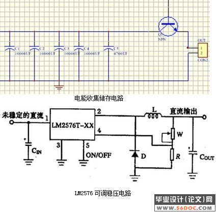
目 录 18000字
第1章 概 述 1
1.1课题研究的背景 1
1.2 国内外发展现状 1
1.3 本课题研究的内容 1
第2章 充电器设计的基本理论 3
2.1 常用充电器的充电方式 3
2.2 电能收集充电器的工作原理 3
第3章 电能收集充电器的硬件设计 4
3.1总体方案的比较与选择 4
3.1.2 系统设计 4
3.2 升压电路和降压电路设计 5
[来源:http://www.think58.com]
3.2.1升压电路 5
3.2.2 降压电路 6
3.2.3 MC34063 8
3.2.4 升压电路测试结果分析 9
3.3 单片机供电电路和稳压电路 10
3.3.1 单片机供电电路 10
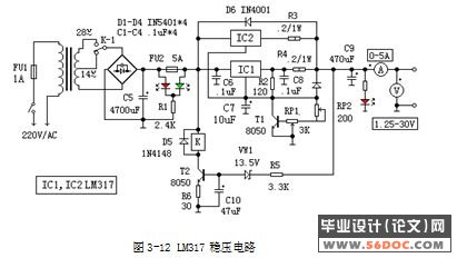
3.3.2 稳压电路 11
3.3.3 LM2576 13
3.4检测部分 15
3.4.1单片机检测电路 15
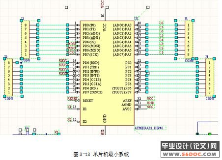
3.4.2 单片机AVR ATmega16 19
3.5电能收集储存电路及设计: 21
第4章 软件设计 22
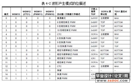
4.1PWM产生的原理 22
4.2产生PWM的相关寄存器 24
4.2.1T/C1 控制寄存器A -TCCR1A 24
4.2.2T/C1 控制寄存器B -TCCR1B 26
4.2.3输出比较寄存器1A-OCR1A 27
4.2.4输出比较寄存器1B-OCR1B 27
4.2.5参数计算 27
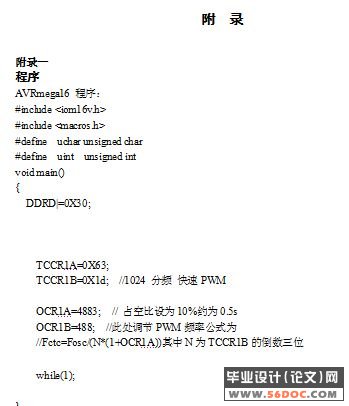
4.2.6程序设计 28
4.3 硬件电路调试 28
[来源:http://think58.com]
4.3.1单片机调试 28
4.3.2电能收集储存电路的调试 28
第5章 总结及展望 29
5.1 总结 29
5.2 展望 29
谢 辞 30
参考文献 31
附 录 32
[资料来源:http://THINK58.com]
[资料来源:THINK58.com]