
分时四驱汽车分动器设计(含CAD零件图装配图)

1.无需注册登录,支付后按照提示操作即可获取该资料.
2.资料以网页介绍的为准,下载后不会有水印.资料仅供学习参考之用.
密 惠 保
分时四驱汽车分动器设计(含CAD零件图装配图)(任务书,开题报告,文献摘要,外文翻译,论文说明书20000字,CAD图5张)
摘 要
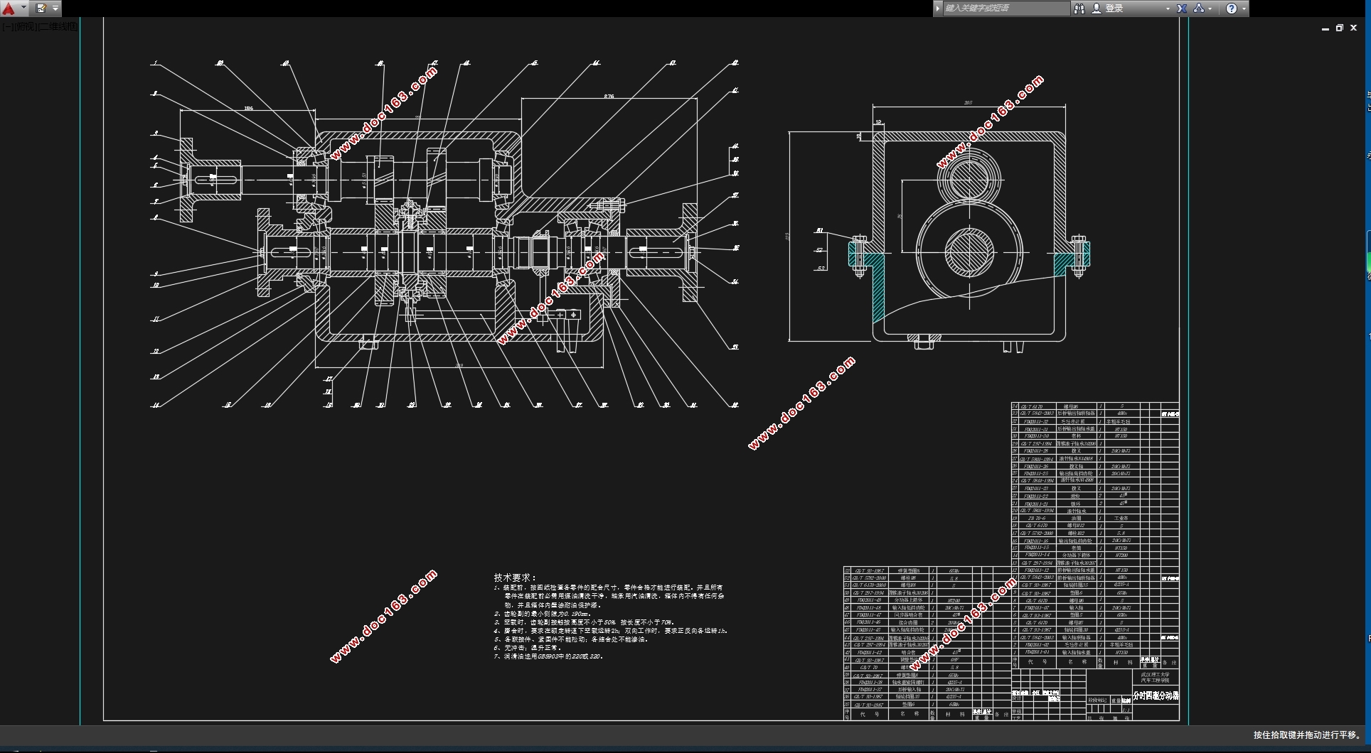
当汽车在无路、泥泞路段或者冰雪路面行驶时,为了充分利用汽车本身的重量来增加汽车车轮与路面的附着力,就必须增加汽车驱动车轮的个数。而分动器的主要功用就是讲汽车从两轮驱动转换成四轮驱动,原理是将是发动机输出的动力分配到前后驱动桥,是扭矩进一步增大;分动器另外一个作用就是可以充当副变速器。分动器的若干个输出轴与输入轴在万象传动装置的作用下与汽车的前后驱动桥相连接,万象传动装置也将分动器的输入轴与输出轴连接。分动器在汽车中的位置是放置在车架上,这是考虑到分动器也是可以被看作成是一个齿轮传动系统。
本次设计需要依据选择的汽车原型,根据他的行驶条件与车辆参数来设计出分动器的结构方案,并且由已知的分动器总成的设计步骤和规范,对分动器的主要零件——齿轮,轴,轴承等进行方案的设计,计算以及校核。并依照汽车理论、机械设计、机械设计手册、汽车设计等参考资料,对设计出的分动器进行具体参数的检验,验证本次设计是否合理、规范、符合实际。最后,用Catia画图软件进行分动器的的三维图的绘制,并用Auto-CAD软件绘制出二维装配图和零件图。
关键词:分动器;分时;中心距;齿轮;轴;轴承。
ABSTRACT
When the car in a blind alley, muddy road driving or snowy roads, in order to make full use of the weight of the car itself to increase the adhesion of the car wheels and the road surface, it is necessary to increase the number of cars driving wheel. The main function of the splitter is to speak from two-wheel drive car converted into a four-wheel drive, the principle is the engine power output will be assigned to the front and rear drive axle torque is further increased; splitter Another role is to act as a deputy transmission. There are a number of splitter output shaft can be connected through the front and rear drive axle Vientiane transmission, the input shaft and the input shaft are connected by a universal transmission device, and also a splitter gear transmission, it is fixed to the frame and placed in on.
The design needs to be based selection of car prototype, according to his driving conditions and vehicle parameters to design the structure of the program splitter and splitter assembly by a known design procedures and specifications of the main splitter parts - design gears, shafts, bearings, etc. programs, computing and checking. And in accordance with the theory of automobile, mechanical design, mechanical design manuals, reference materials and other automotive design, the design of the splitter to test specific parameters, verification of this design is reasonable, standardized, realistic. Finally, Catia software splitter drawing a three-dimensional map drawing, and draw two-dimensional assembly drawing and detail drawing with Auto-CAD software.
Key words: Transfer;points;center distance;gear;axis;bearing.
分动器设计参数
项 目 参 数
最高时速 180km/h
轮胎型号 225/65R17 102T
发动机型号 R20A1
最大扭矩 220Nm
最大扭矩转速 4200rpm
最大功率 125Kw
最大功率转速 5800rpm
最低稳定车速 5Km/h
最低稳定转速 980r/min
汽车整备质量 1630kg
汽车满载质量 2479kg
[来源:http://think58.com]
目 录
摘要 ………………………………………………………………………………………Ⅰ
Abstract……………………………………………………………………………………Ⅱ
[资料来源:http://www.THINK58.com]
第1章 绪论 ……………………………………………………………………………1
1.1 选题背景 ………………………………………………………………………1
1.2 分动器简介 ……………………………………………………………………2
1.2.1 分动器的类型………………………………………………………………3
1.2.2分动器的构造和原理………………………………………………………4 [资料来源:www.THINK58.com]
1.3 分动器的设计思想 ………………………………………………………………4
1.4 本设计主要完成的内容 …………………………………………………………5
第2章 分动器设计的总体方案 ……………………………………………………6
2.1 分动器结构方案的选择…………………………………………………………6
2.1.1 传动机构布置方案分析…………………………………………………6
2.1.2 零部件结构方案分析………………………………………………………6
2.2设计依据 …………………………………………………………………………8
2.2.1 挡数的确定 ………………………………………………………………9
2.2.2 传动比的确定 ……………………………………………………………10
2.2.3 分动器中心距的确定 ……………………………………………………11 [资料来源:www.THINK58.com]
2.3 本章小结 ………………………………………………………………………11
第3章 主要零部件的设计及计算 ………………………………………………13
3.1 齿轮的设计及校核 ……………………………………………………………13
3.1.1 齿轮参数确定及高低挡齿轮齿数分配 …………………………………14
3.1.2 轮齿强度计算……………………………………………………………16
3.1.3 分动器齿轮的材料及热处理……………………………………………17
3.2 轴的设计及校核…………………………………………………………………18
3.2.1 轴的失效形式及设计准则………………………………………………18
3.2.2 轴的设计…………………………………………………………………19
3.2.3 轴的校核…………………………………………………………………20
[资料来源:http://www.THINK58.com]
3.3 轴承的选用及校核………………………………………………………………22
3.3.1 分动器轴承型式的选择………………………………………………… 22
3.3.2 轴承的校核………………………………………………………………22
3.3.3 轴承的润滑和密封………………………………………………………24
3.4本章小结………………………………………………………………………24
[资料来源:http://think58.com]
第4章 分动器其他零件及机构的设计 …………………………………………25
4.1 同步器的设计及计算……………………………………………………………25
4.2 惯性式同步器 …………………………………………………………………25
4.2.1锁环式同步器的结构 ……………………………………………………25
4.2.2锁环式同步器的工作原理 ………………………………………………25
4.2.3锁环式同步器主要尺寸的确定 …………………………………………27
[来源:http://www.think58.com]
4.3主要参数的确定 …………………………………………………………………28
4.3.1摩擦因f …………………………………………………………………28
4.3.2同步环主要尺寸的确定 …………………………………………………28
4.3.3锁止角 …………………………………………………………………31
4.3.4同步时间 …………………………………………………………………31
[来源:http://www.think58.com]
4.3.5转动惯量的计算 …………………………………………………………31
4.4 本章小结…………………………………………………………………………31
结论 ………………………………………………………………………………………32
参考文献………………………………………………………………………………… 33
致谢 ………………………………………………………………………………………34
[版权所有:http://think58.com]
上一篇:纯电动6120BEV旅游客车悬架系统设计(含CAD图,CATIA三维图)
下一篇:城市微型纯电动皮卡车架有限元分析及结构优化(含CAD图,CATIA三维图)