
传真机左支架多工位级进模设计(含CAD零件图装配图)

1.无需注册登录,支付后按照提示操作即可获取该资料.
2.资料以网页介绍的为准,下载后不会有水印.资料仅供学习参考之用.
密 惠 保
传真机左支架多工位级进模设计(含CAD零件图装配图)(开题报告,中期检查表,论文说明书10900字,CAD图12张)
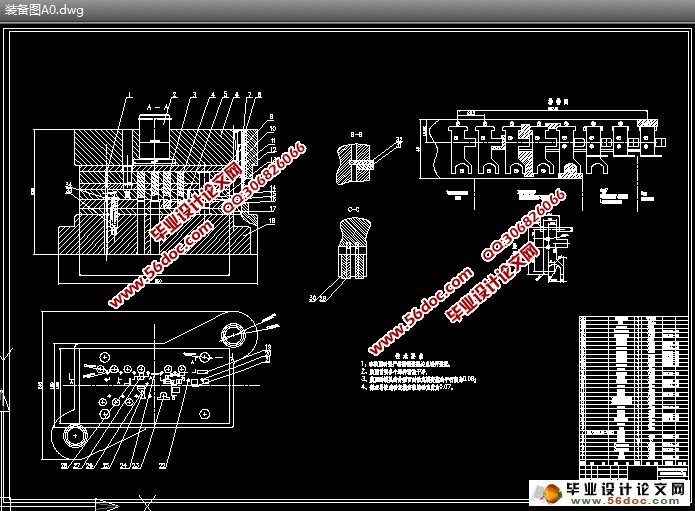
摘 要:本毕业设计是对传真机左支架的工艺进行整体分析, 在这个基础上设计出一副能生产出合格产品的设计计算。此级进模工艺主要有冲孔、切边、弯曲,模具设计主要包括排样设计,凸凹模刃尺寸的设计计算、冲压力的计算及模具压力中心的确定、模具非标准件的设计计算、压力机的选择及其校核。
关键词:工艺、级进模、冲孔、切边、弯曲、凸凹模、刃口、设计计算
The Design Of Multi-Position Progressive Die For Fax Left Bracket
Abstract:This graduationproject aims at the global analysis of craft for the left support of facsimile machines.Based on this,one pair of design calculation has been designed,which can manufacture standard products.This progressive die process includes punching holes,trimmings and curving.layout design,the design clcullation of convex-concave mold cutting edge size,dtamping force calculation and the determination of die pressure center are included in die design.The design calculation of non-standard did,the selection and check of mechanical press are also contained in this.
[来源:http://think58.com]
Key words: craft,the level enters the mold, punch holes, curving, convex-concave mold, cutting edge, design calculation
[来源:http://think58.com]
目 录
摘要……………………………………………………………………………1
[版权所有:http://think58.com]
关键词…………………………………………………………………………1
1前言……………………………………………………………………………2
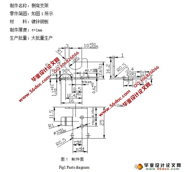
2制件分析……………………………………………………………………3
2.1制件结构分析 …………………………………………………………………3
2.2制件工艺分析 ……………………………………………………………………3 [来源:http://www.think58.com]
3冲压工艺方案的确定……………………………………………………………………4
3.1排样的设计计算 …………………………………………………………………5
3.2冲压力的计算 …………………………………………………………………5
3.2.1凸模厚度 …………………………………………………………………5
3.2.2计算冲裁力 ………………………………………………………………6
[资料来源:http://THINK58.com]
3.2.3弯曲力的计算 ……………………………………………………………8
3.2.4制件与板料分离 …………………………………………………………8
3.3模具压力中心的计算 ……………………………………………………………9
3.4弯曲回弹的计算 …………………………………………………………………10
4模具设计计算……………………………………………………………………10 [资料来源:http://think58.com]
4.1凸凹械刃口尺寸的确定 …………………………………………………………11
4.1.1 A区凸凹模的刃口尺寸确定……………………………………………11
4.1.2 B区凸凹模的刃口尺寸确定……………………………………………12
4.1.3 C区凸凹模的刃口尺寸确定……………………………………………14
4.1.4 D区凸凹模的刃口尺寸确定……………………………………………15
[版权所有:http://think58.com]
4.1.5 E区凸凹模的刃口尺寸确定……………………………………………16
4.1.6 F区凸凹模的刃口尺寸确定……………………………………………17
4.2弯曲凸模工作部分的尺寸计算…………………………………………………18
4.3凸凹模的结构设计 ……………………………………………………………20
4.3.1 凸模结构设计……………………………………………………20
[来源:http://www.think58.com]
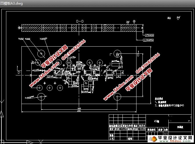
4.3.2 凹模结构设计……………………………………………………21
4.4定位、导向、推荐、卸料装置的设计……………………………………………21
4.4.1 导正销……………………………………………………22
4.4.2 浮动导杆……………………………………………………22
4.4.3 导向零件……………………………………………………22
4.4.4 卸料推件装置……………………………………………………23
5模具闭合高度的计算和校核及压力机的选择…………………………………………23
5.1模具闭合高度的计算 ……………………………………………………………23
5.2压力机的选择及校核 ……………………………………………………………23
6结论………………………………………………………………………………………24 [资料来源:http://www.THINK58.com]
参考文献 ………………………………………………………………………25
致谢……………………………………………………………………………26
[来源:http://think58.com]
上一篇:孔用弹性挡圈多工位级进模设计(含CAD零件图装配图)
下一篇:收录机机芯的开门推板多工位级进模设计(含CAD零件图装配图)